In the high-performance computing space, the smooth transmission of visual data from a processing GPU to a high-density monitor panel is governed by strict protocol architectures. When data professionals, software engineers, or high-frequency scalpers interact with screen diagnostic platforms like laptoptech.online, they are executing specialized scripts designed to verify real-time pixel integrity. Moving past basic physical connections, achieving maximum frame delivery and color depth requires a comprehensive understanding of Signal Protocol Engineering.
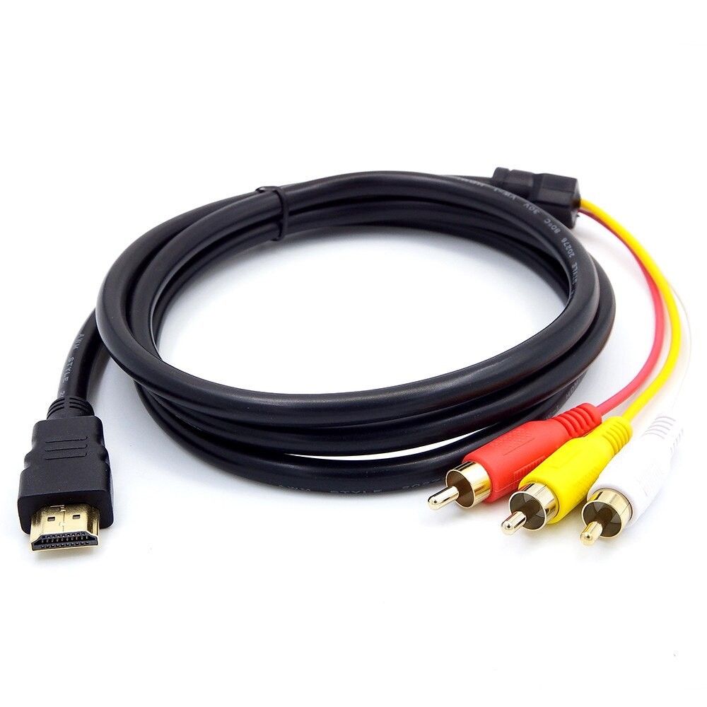
For infrastructure systems engineers configuring multi-display command stations, and hardware analysts auditing device bandwidth configurations using catalogs like laptoptechinfo.com, understanding cable protocols is essential. Setting up hardware monitors using unverified adapters or outdated cable standards frequently results in screen flickering, forced drops in refresh rates, and compression artifacts that degrade text readability.
This technical guide delivers an exhaustive breakdown of HDMI versus DisplayPort signaling frameworks, deconstructs the mathematics of raw pixel bandwidth calculations, and analyzes how data compression protocols maintain link stability.
1. The Core Architectures of Visual Signaling Protocols
To understand how high-resolution images reach your monitor, you must analyze the two dominant digital transmission standards: HDMI (High-Definition Multimedia Interface) and DisplayPort. While both cables look similar from the outside, their internal data transmission engines use completely different engineering frameworks.
+-------------------------------------------------------------+
|              [ PROTOCOL SIGNALING METHODS ]                 |
+-------------------------------------------------------------+
|                                                             |
|  [HDMI Engine]        ===> TMDS / FRL (Fixed Frame Packets) |
|                       ===> Pin-to-Channel Locked Routing     |
|                                                             |
|  [DisplayPort Engine] ===> Packetized Data Architecture     |
|                       ===> Micro-Packet Network Routing     |
|                                                             |
+-------------------------------------------------------------+
HDMI: Consumer-Centric TMDS and FRL Engineering
HDMI was originally developed by a consortium of consumer electronics companies to standardize television and audio connections.
- TMDS (Transition-Minimized Differential Signaling): Traditional HDMI standards (up to HDMI 2.0) utilize TMDS signaling. This architecture uses three dedicated video data channels along with a separate clock channel. The system encodes 8-bit pixel data into 10-bit packets to minimize signal degradation over long cable runs.
- FRL (Fixed Rate Link): Introduced with the modern HDMI 2.1 standard, FRL replaces TMDS. It eliminates the dedicated clock channel, turning it into a fourth active video data lane. FRL packages data into fixed-size blocks similar to network packets, allowing HDMI 2.1 to scale up to an impressive 48 Gbps of total bandwidth.
DisplayPort: The Packetized Data PC Standard
Developed by the Video Electronics Standards Association (VESA), DisplayPort was engineered from day one specifically for advanced computer monitor setups.
Unlike HDMI’s synchronized clock design, DisplayPort operates like an internal PCIe network card or local ethernet connection. It breaks video and audio data down into micro-packets called Stream Packets and transmits them across 1, 2, or 4 independent data lanes.
Because DisplayPort is completely packet-based, a single cable can natively split its bandwidth across multiple downstream monitors using a protocol called Multi-Stream Transport (MST). This allows developers to daisy-chain multiple displays from a single GPU output port without running extra cables back to the computer chassis.
2. The Mathematics of Pixel Bandwidth Calculations
To determine whether a specific cable protocol can support a high-performance monitor setup (such as a $4\text{K}$ resolution running at a smooth $144\text{Hz}$ refresh rate), we must calculate the Total Raw Data Bandwidth required by the display.
The Raw Bandwidth Formula
The data throughput requirement of any digital display panel is a direct mathematical result of four core variables:
$$\text{Total Bandwidth} = H_{\text{Total}} \times V_{\text{Total}} \times \text{Refresh Rate} \times \text{Color Depth} \times 3$$
Where:
- $H_{\text{Total}}$ represents the total horizontal pixels including the Blanking Interval padding.
- $V_{\text{Total}}$ represents the total vertical pixels including the blanking padding.
- Color Depth represents the bits-per-pixel assigned to each individual color channel (typically 8-bit or 10-bit).
- The multiplier 3 represents the three primary sub-pixel color channels (Red, Green, Blue).
Real-World Bandwidth Calculation Simulation
Let’s run an illustrative example calculation for a high-end workstation display setup to see how much data must move through the cable stream every second:
- Active Panel Resolution: $3840 \times 2160$ ($4\text{K}$ Ultra HD)
- Total Dimensions Including Blanking Interval ($H_{\text{Total}} \times V_{\text{Total}}$): $4000 \times 2222$ pixels
- Target Refresh Frequency: $144\text{Hz}$
- Target Color Precision: 10-bit High Dynamic Range (HDR) color tracking
Let’s plug these metrics into our bandwidth calculation engine:
Step 1: Calculate the total number of pixels processed per second
$$\text{Pixel Rate} = 4000 \times 2222 \times 144 = 1,279,872,000 \text{ pixels/second}$$
Step 2: Multiply by the color data constraints per pixel
$$\text{Total Bits Per Pixel} = 10 \text{ bits} \times 3 \text{ channels} = 30 \text{ bits/pixel}$$
Step 3: Compute the final raw data throughput requirement
$$\text{Raw Bandwidth} = 1,279,872,000 \times 30 = 38,396,160,000 \text{ bits/second} \approx \mathbf{38.40 \text{ Gbps}}$$
The Protocol Compatibility Check
Our math proves that running a $4\text{K}$ resolution at $144\text{Hz}$ with 10-bit color requires a steady transmission stream of $38.40\text{ Gbps}$.
If a user attempts to run this monitor setup using an older HDMI 2.0 cable connection (which is strictly capped at an $18.0\text{ Gbps}$ bandwidth ceiling), the system will face a hardware bottleneck. The operating system will be forced to downscale the display metrics—either dropping the refresh rate to a choppy $60\text{Hz}$ or lowering the color precision down to a standard 8-bit space.
By referencing these bandwidth equations, and utilizing the real-time configuration utilities on laptoptech.online, users can pinpoint these protocol limitations instantly before purchasing expensive hardware components.
3. High-Bandwidth Data Compression: Decoding DSC Architecture
As display resolutions climb to $8\text{K}$ and refresh rates scale toward $240\text{Hz}$ and beyond, the data requirements quickly outrun the physical bandwidth limits of standard copper cables. To solve this engineering challenge, VESA developed an advanced data compression standard known as Display Stream Compression (DSC).
The Visually Lossless Compression Loop
Unlike standard image compression algorithms (like JPEG or MP4) which can leave visible blurriness or compression artifacts around text lines, DSC is a real-time, hardware-level Visually Lossless protocol.
DSC processes incoming frame data on the fly, compressing the data stream at a constant 3:1 ratio before sending it through the cable. The monitor’s internal scaler hardware then decompresses the packets instantly with a ultra-low latency footprint measuring under $1\text{ microsecond}$.
[ GPU Frame Buffer ] ---> [ DSC Hardware Encoder (3:1) ] ---> [ Cable Pipeline ] ---> [ Monitor Decoder ]
Preserving Sharp Text: The Chroma Subsampling Factor
When DSC is not available on older hardware connections, graphics cards often rely on a crude fallback compression method called Chroma Subsampling to save bandwidth. This method reduces color data in the image while keeping brightness data intact, and is denoted by ratios like 4:4:4, 4:2:2, or 4:2:0.
- 4:4:4 (Uncompressed Baseline): Every single pixel on the screen receives its own independent brightness and color coordinates. This is the mandatory standard for computer monitors, ensuring that fine text lines and source code render with sharp edges.
- 4:2:0 (Compressed Fallback): The color resolution is cut in half horizontally and vertically, sharing color data across blocks of four adjacent pixels. While this works acceptably for video files, it causes severe Color Fringing on computer screens. Sharp text lines will appear blurred with red or blue shadows, causing noticeable eye fatigue during extended coding or reading sessions.
4. Multi-Platform Network Geometry and System Synchronization
Building, hosting, and optimizing real-time hardware testing utilities, calculation databases, and interactive documentation platforms requires maintaining a highly synchronized infrastructure across your entire web network.
Multi-Property System Architecture Mapping
- Real-Time Display Diagnostics: For interactive web applications like laptoptech.online, providing fast, lightweight interface scripts allows users to verify signal timings and pixel tracking instantly. This high-utility focus keeps visitors on the page longer, creating an ideal layout environment for native ad monetization via networks like Revbid.
- High-Precision Quantitative Calculators: For utility-centric tracking setups like secretgem.site, providing high-performance position size calculators ensures that active traders can instantly calculate their risk parameters without experiencing execution delays or interface lag.
- Hardware Benchmarking and Review Analysis: For data directories like laptoptechinfo.com, understanding display and hardware physics allows you to publish detailed technical guides analyzing processor thermal efficiency against demanding scripting workloads.
- The Center for Advanced Software Strategy: Publishing technical articles on script optimization, database performance, and interface design helps establish MyTechHub.Digital as an authoritative destination for modern developers.
Furthermore, executing complex calculation scripts, updating real-time web widgets, and tracking high-frequency trading feeds simultaneously requires a physical setup with strong processing power and optimized system architecture. To learn how to select hardware components that can comfortably sustain intensive programming or high-frequency calculation workloads without thermal degradation, check out the hardware analysis guides over at laptoptechinfo.com.
5. System Troubleshooting: Diagnosing Digital Signal Degradation
When high-bandwidth signal streams run through physical cables, they are vulnerable to electromagnetic interference (EMI) and signal attenuation. Understanding the physical symptoms of cable failure allows power users to fix display issues systematically.
Common Signal Failure Symptoms
- Digital Sparkles (Pixel Artifacts): This occurs when specific bits in the data packets are corrupted during transmission across the cable. Users will see tiny, random white or colored pixels flashing across dark areas of the screen. This is a clear warning sign that the cable is operating right at the absolute limit of its physical integrity.
- Display Blackouts (Handshake Drops): If the signal degradation drops too low, the monitor’s internal receiver circuit can lose track of the data stream entirely. The screen will instantly go black for a few seconds while it attempts to re-establish a secure HDCP cryptographic handshake with the host GPU.
- Forced Protocol Downgrades: Modern operating systems are smart enough to detect high link error rates over poor connections. If a cable cannot reliably sustain high speeds, the graphics driver will automatically lock out your monitor’s top performance settings, preventing you from choosing your screen’s maximum refresh rate until the link is stable.
Step-by-Step Resolution Protocol
- Isolate the Signal Path: Remove any unverified extension cables, third-party switch boxes, or passive display dongles from your setup. Connect the high-performance monitor directly to your GPU’s native output port using a single premium cable.
- Verify Cable Certification: Ensure your cables match official industry performance standards. For HDMI connections, look for certified Ultra High Speed cables; for DisplayPort connections, use cables explicitly rated for DP 2.1 (UHBR10/20) data metrics.
- Manage Cable Length Constraints: Keep high-bandwidth passive copper cables short—ideally under 2 meters (6.5 feet). If your physical workspace layout requires a longer cable run, upgrade to an active fiber-optic (AOC) cable to prevent signal loss over long distances.
6. Comprehensive Signal Protocol Comparison Matrix
To wrap up, this technical matrix compares the key data capacities, signaling formats, and structural features of the leading display protocol standards available today:
| Protocol Standard | Maximum Bitrate Capacity | Signaling Engine Format | Key Feature Value | Core Structural Weakness | Main Targeted Workspace |
| HDMI 2.0 | $18.0 \text{ Gbps}$ Baseline | TMDS (3 Data Lanes + 1 Clock Lane) | Universal consumer electronics compatibility. | Lacks native support for multi-stream daisy-chaining. | Standard office productivity and baseline media streaming. |
| HDMI 2.1 | $48.0 \text{ Gbps}$ Maximum | FRL (4 Fixed Rate Data Lanes) | High bandwidth ceiling with Dynamic HDR support. | Requires strict licensing fees for hardware integration. | Premium console gaming and high-end home theater setups. |
| DisplayPort 1.4a | $32.4 \text{ Gbps}$ Peak | Packetized Data Architecture | Native Multi-Stream Transport (MST) daisy-chaining. | Prone to unseating if using low-quality cables without latches. | Multi-monitor programming rigs and financial trading desks. |
| DisplayPort 2.1 | $80.0 \text{ Gbps}$ Maximum | Packetized Data (UHBR Standards) | Maximum bandwidth ceiling supporting native $8\text{K}$ streams. | Limited availability on older legacy graphics hardware. | Ultra-high-refresh simulation and cutting-edge engineering stations. |